
The Setups and Toolpaths for 3D inlays are very similar to 2D inlays. I’ll only discuss what is different from 2D Inlays, so please read Pocket Setup - 2D first.
Setup
The main difference between 2D and 3D inlays is the Setup’s Stock Solid is a 3D object. Consider machining this 3D inlay pocket for a tree on the handle of this spatula (from Digital Files: Wok Spatula)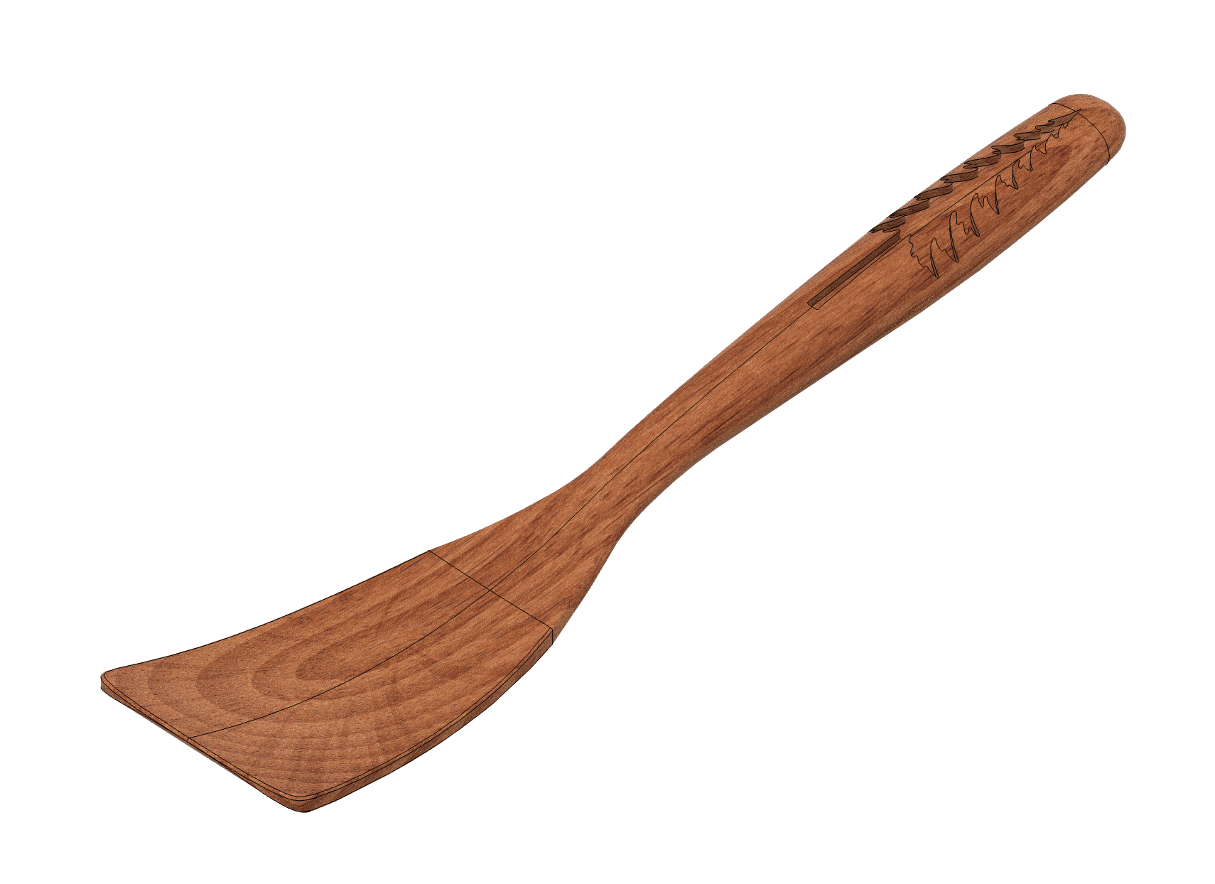
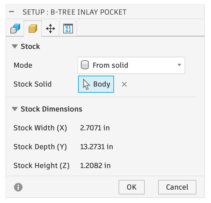
Setup: Stock mode set to 'From solid'
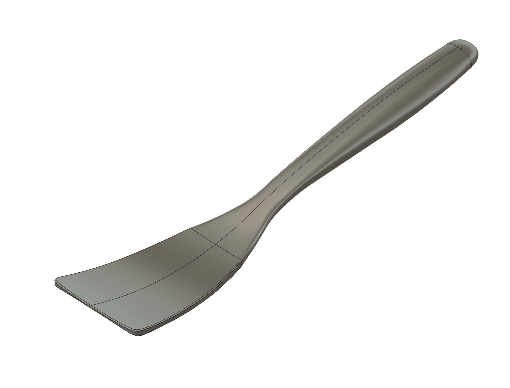
The solid body that is the stock
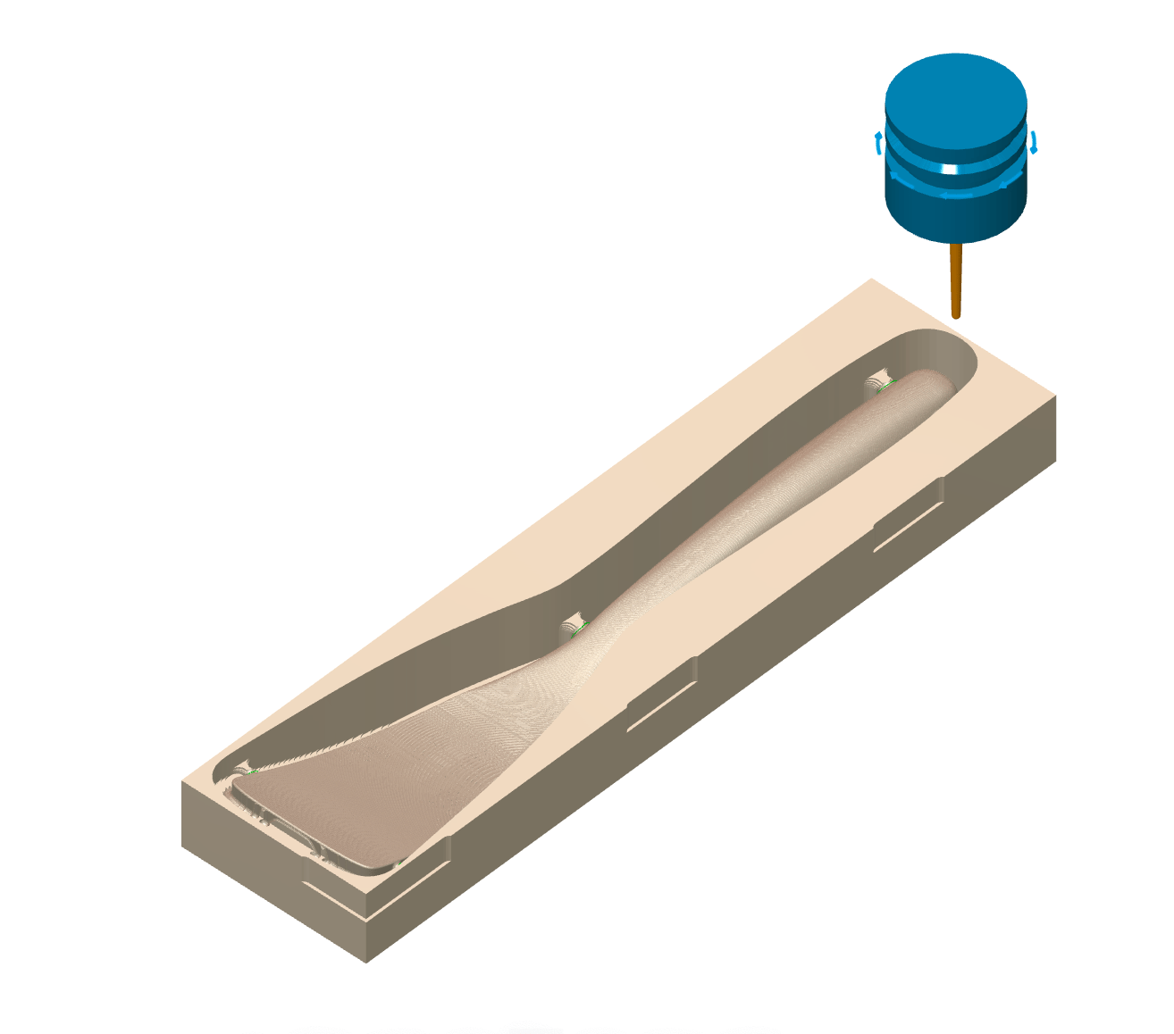
It is important to use the same origin for your inlay pocket and the machining that got you your initial shape!
Toolpaths
The 3D toolpaths work very differently from the 2D toolpaths, as they have to follow the 3D contours of your target body.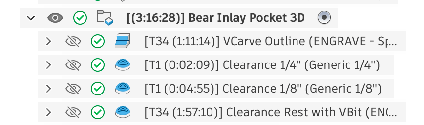
1. VCarve Outline
This is a 3D Pencil Toolpath in Autodesk Fusion using your VBit to do a VCarve. The important part is the Gemoetry Tab. The Machining Boundary Selection is set to a Sketch Profile, and the Design Sketch in the Pocket component is selected (this is similar to the 2D Pocket’s setup).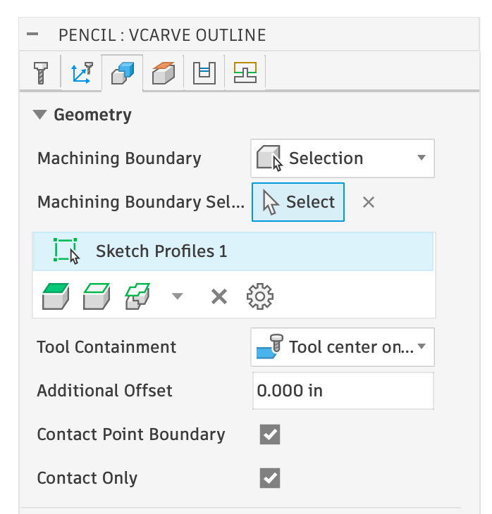
On the Geometry tab, the Machining Boundary Selection is set to Sketch Profiles.
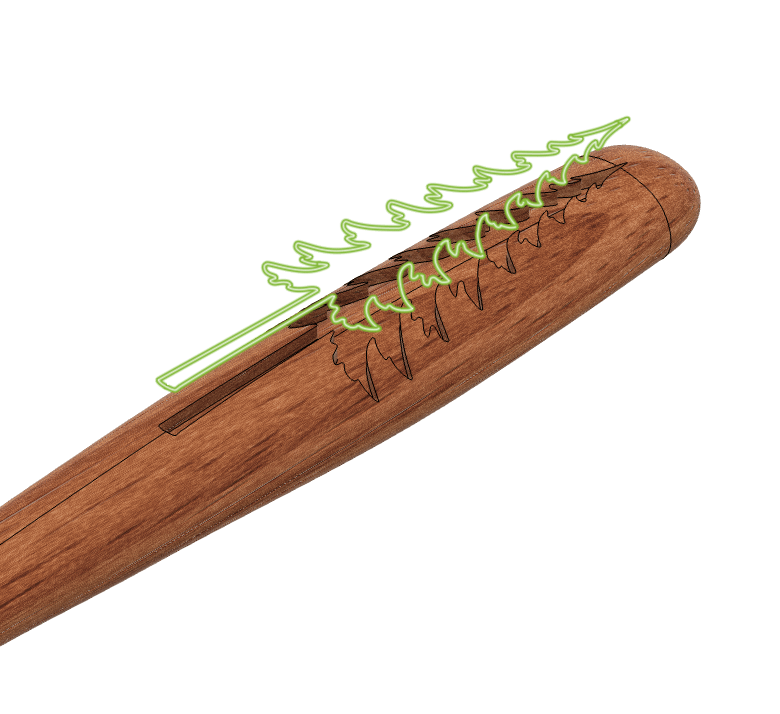
The Sketch Profiles highlighted (green)
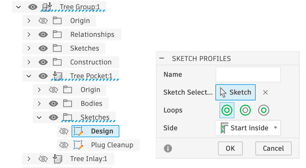
The Design Sketch is selected
2. Clearance Toolpath - Largest Bit
The first clearance toolpath is a 3D Scallop Toolpath. The important part is the Gemoetry Tab. The Machining Boundary Selection is set to the same Sketch Profile as the last toolpath. However, Tool Containment is set to Tool Inside Boundary and an Additional Offset Value is set to a specific number (0.0230” in this example). This value is an Expression, which you can see by clicking the three dots next to it and editing it. The Expression is set to the Parameterpocket_stock_to_leave, which is a basic mathmatical equation based on other parameters: tan(inlay_bit_angle / 2.0) * inlay_depth.
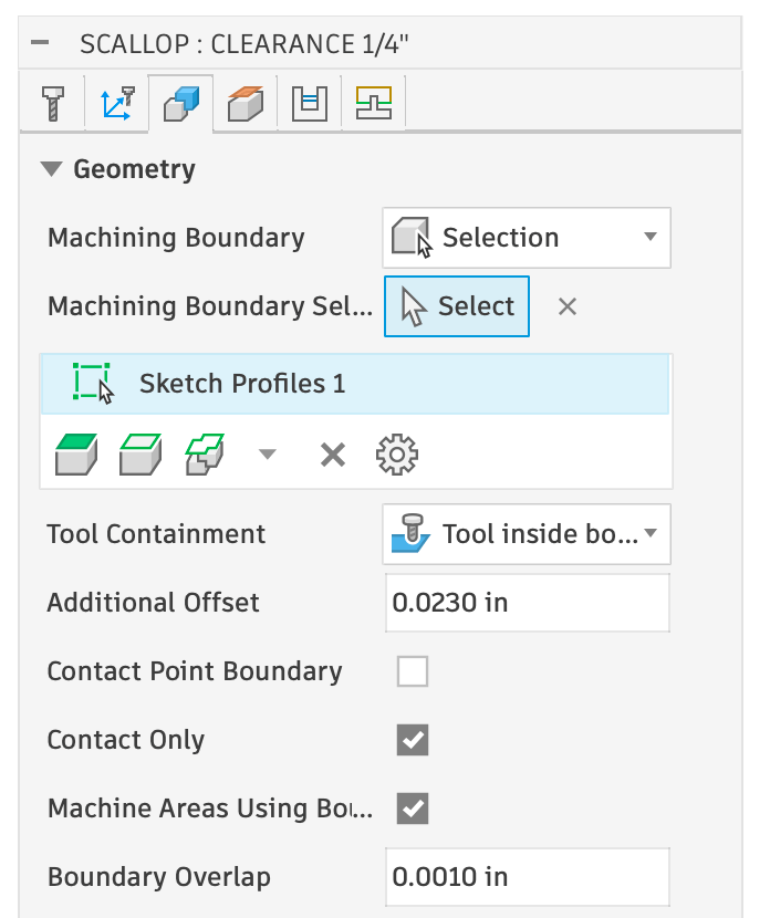
On the Geometry tab, the Machining Boundary Selection is set to Sketch Profiles.
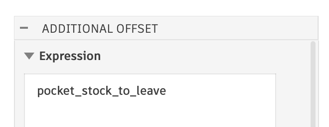
Additional Offset Expression
3. Additional Clearance Toolpaths
Additional clearance toolpaths will be added for each additional smaller diameter bits you checked. The only difference in these toolpaths is they have Rest Machining turned on.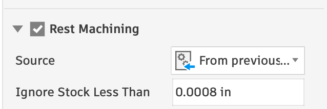
4. Clearance Rest with VBit
This is another Scallop toolpath setup with the same VBit you initialy picked and it’s purpose is to remove all the material that the previous clearance toolpaths could not get to. It is also constrained by the same Design sketch and has Rest Machining turned on. What is different is the Tool Containment is set to center and the additional offset is-pocket_stock_to_leave (negative pocket stock to leave - which is the same math as before). Fusion treats negative values to be on the inside of a “center” tool containment.
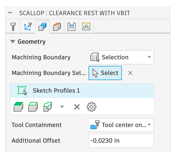
Multiple Depths or Roughing with Pencil
Most toolpaths have “Multiple Depths”, but Pencil does not. To work around this, right click on the Pencil toolpath and select Duplicate. Rename the first one “VBit Rough”. Double click on it to edit it. On the Passes tab, check** Stock to Leave** and set the Axial Stock to Leave to be half your inlay depth. IE: if your depth is 0.200”, set it to 0.100”.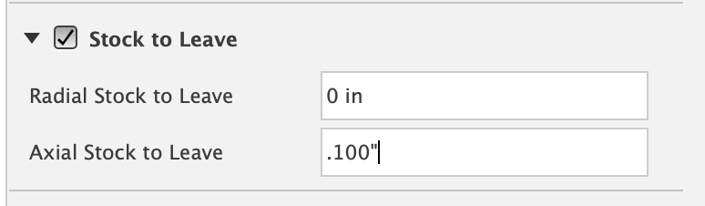
Toolpath Reordering
The default order would be: V-bit, Clearance Bit, V-bit. This causes an unnecessary tool change back to the V-bit at the end. However, moving the last “Clearance Rest with VBit” operation above the Clearance operation will cause it to re-calculate and not be correct (it’d try to remove everything the clearance should be doing). To solve this, you can right click on the V-bit Rest operation and check Protect. It will show Protected via a lock icon. You can then drag the protected toolpath above the Clearance operation.If you do this, and you change something that makes the toolpaths need recalculation, you will have to move it back and unprotect it.
VBit First or Clearance First
I prefer to do the v-bit portion first, and finish with the clearance bit. Some people prefer to do the Clearance operation first. If you want to do this, you can just drag the clearance operation(s) before the VBit Outline. If you do that, you won’t have to Protect the V-bit Rest.Need help? Join Corbin’s Facebook group CNC Woodworking or email corbin@corbinsworkshop.com